Wind Turbine Optimization
Overview
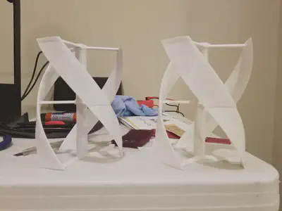
As a part of IB Physics SL I at my high school, students were tasked with designing and conducting a science fair experiment. I had just set up my 3D printer at home, so I wanted to do a project related to renewable energy that would be aided by the rapid prototyping capabilities I had gained. After some research, I determined that it would be feasible to 3D print scale Gorlov helical wind turbines and test them in a wind tunnel to determine the optimal blade width for maximum voltage output.

Details
In my initial research, I found that there were many styles of wind turbines. Primarily, they can be categorized into two main groups: horizontal-axis wind turbines (HAWT) and vertical-axis wind turbines (VAWT). Vertical axis wind turbines have about the same efficiency as horizontal axis wind turbines with the exception that they are more convenient for maintenance, particularly in commercial applications or when operating in differing weather conditions. Since the goal of developing and deploying wind turbines is to compete with the omnipresence of coal and oil-based generators, wind turbines should be designed such that they can be manufactured cheaply and as simple to maintain as possible.
Furthermore, vertical axis wind turbines can be further split into drag-based and lift-based vertical axis wind turbines. Drag based turbines are typically much less efficient than lift-based turbines, so I chose to focus solely on VAWT that are lift-based. The most common lift-based vertical axis wind turbine is the Darrieus VAWT, which has two thin, airfoil-shaped blades that are curved outward from the base to the top. The blade shape of Darrieus turbines is called Troposkien, meaning “turning rope” and looks like an eggbeater. Darrius turbines operate by having air travel along the outside of the blade at a higher speed than the inside edge of the blade, creating an area of lower pressure on the outside of the blade. This area of low pressure creates a net force on the blade perpendicular to the outside of the blade. Angled correctly, this net force can be used to turn the turbine.
However, this lift-based design has a few flaws. The main problems with the Darrieus style blade are vibration generation and noise output. In the typical Darrieus turbine setup, as the blades rotate, the angle of attack will change, resulting in areas throughout the rotation where the blade is in a stall. This causes vibrations which reduce the life of the turbine, along with causing noise which is especially unwanted in urban settings. Since VAWTs have only been in development for the past decade, they have had little usage in large-scale production usage. In urban usage, these turbines do not have to be scaled up to large sizes to meet electrical output quotas. For this reason, the vibrations are not as problematic, and are only a minor nuisance in the noise level. However, if these turbines are scaled up to wind-farm size, then these vibrations can cause the central axis of the turbine to shear off its mount, effectively terminating an expensive investment in renewable energy.
In order to solve these problems, a hydro-turbine developed by Alexander M. Gorlov was modified to follow the same guiding principles of the Darrieus VAWT, but without the weakness of excessive vibrations being caused by having positions where the entire blade can be stalled. Gorlov’s design solves this problem by curving the Troposkien blades of the Darreius design in a helical fashion, allowing for some part of the blade to always be actively generating lift, even if other parts are in a stalled position. This greatly reduces the vibrational effects caused by a stalling blade. Furthermore, Gorlov VAWT are the only turbines currently in use that can generate up to 10 kW of electrical output when scaled for urban usage. For the aforementioned reasons, Gorlov vertical axis wind turbines were the style of turbine chosen for this experiment.
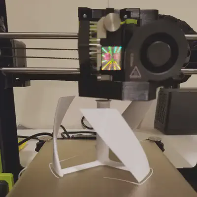
After finishing the background research, the turbines were modeled in Fusion 360, with the blade width being varied for each design. Since I was limited by the build volume of my printer, the models had to be split in half and printed in two parts.

While the models were printing, I set up a wind tunnel at home from foamboard, a box fan, and some cardboard tubes as flow straighteners. In the testing chamber, I added a 12-volt DC motor that was then connected to a multimeter to measure the voltage output of the turbines in motion. After assembling the printed turbine halves, I began testing. Below is a video taken during experimentation.
Through testing in the wind tunnel, it was determined that the smallest blade width, 23.75 mm from leading to trailing edge, produced the greatest electrical output. This was contrary to my hypothesis that the largest blade width would produce the greatest electrical output due to having a larger surface area to generate lift on. It is possible that this is a result of the increased mass of the larger blade width wind turbines. Though the lift force may have increased due to having a greater surface area on the larger blade width turbines, the mass also increased. If the mass increased at a greater rate than the force of lift, the angular acceleration of the turbines would be lower, resulting in less voltage output.
If you would like to read the full paper, please send me an email!